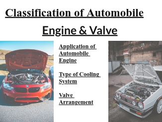
The Classification of Automobile Engine describes the fundamental operating principles in internal combustion engines categorized below.
CARSUFFER.COM
- Application of Automobile Engine
- Type of Cooling System
- Valve Arrangement
Application of Automobile Engine
Basically, the automobile engines are the same but for different application adjustments in fuel delivery is controlled in such a way that the engine can deliver the power in that working condition.
Broadly speaking the engines are classified into two categories these are:-
- constant speed engine
- variable speed engine
1. constant speed engine
These are used in touch applications when these are supposed to run at constant speed delivering constant horsepower for a long time.
Since these engines run at maximum speed delivering constant horsepower as such engine rating is approximately 10% less than a variable speed engines search engines are used for generation of electricity or on, such machines which demand running the engine at a constant speed.
2. variable speed engine
These engines are also known as Automotive engines these engines are related to developing more power than constant speed engines reason being that we run the engine for short time at maximum speed as you must have noticed when during the automobile that we go on increasing and decreasing speed to Sweet road and load condition.
Apart from the above said two times mention sometimes intermediate type usually called as agricultural application type is also rated in between these two types to suit its application for the agricultural machine where at time engine is made to run at a constant speed at a stretch and then slow down.
Type of Cooling System
Engines are classified as to whether they are air-cooled or water-cooled we will discuss the cooling system in more detail in the cooling system chapter but never the less let us understand the basic difference.
- Air-cooled engine
- Water-cooled engine
1. Air cooled engine
An air-cooled engine, the air is only cooling media to dissipate the heat produced during power stroke all the air-cooled engine is not normally used in cars and trucks but are mostly used in a two-wheeler, three-wheeler, and aircraft engines.
In this type of engine, cylinders are cool by conducting the heat to metal fins on the outside of the cylinder wall and heat through the air passing around it.
These engines are usually placed in a way that they are exposed to the stream due to the running of the vehicle sometimes fan or blower is also installed to direct more air around the hot area.
2. Water cooled engine
Water-cooled engines require a water jacket around the cylinder combustion chamber and the valve ports in which water is made to flow the heat collected by water is dissipated through the radiator and fan.
Valve arrangement
Classification of Automobile Engine is according to the position to intake and exhaust valve whether they are fitted in the cylinder block or in the cylinder for this various arrangement use are given below.
Cylinder head design with respect to Valve fitting
The cylinder head is classified into five categories with respect to Valve fitting this is also under:-
- I-head
- H-head
- F-head
- T-head
- L-head
1. I-head
Both valves are fitted above the cylinder in the cylinder head this system is commonly known as a valve in the head or overhead valve engine.
In this arrangement push-rod and Rockers arm are required to reverse the direction of wall moment and require only one camshaft to operate both valve inlet and exhaust.
In most of the engines, the camshaft is fitted in the cylinder block while some engine employee overhead camshaft run with the help of timing Chain and timing belt this system is mostly used in the automobile as both the valve are most effective in this position.
2. H-head
Both the valve is fitted over the cylinder at a certain angle to each such arrangement is used in V block engines.
3. F-head
In this design one valve is fixed on top of the cylinder in the cylinder head while the other one is placed in the block in most of the engine intake wall is usually fit in the head while the exhaust valve is located in the engine block in this case overhead valve is operated through pushrod rocker arms.
While the exhaust valve fitted in the block is active directly e-bike camshaft by Tapit this system is not very commonly used as gases get pocketed over this area and homogeneous burning of gases cannot be achieved this system is used in petrol Jeep.
4. T-head
In this case, both the valve are placed in the block as such two pockets are formed in the arrangement of camshaft where required for operating inlet valve while the other for operating exhaust valve on another side this system was used in the old vehicle but is not used nowadays.
5. L-head
Both the valve inlet and exhaust are fitted on one side of the block the valve operating machine is located directly below.
The valve and one camshaft operate both the valve with this arrangement pocketing of charge inexperienced.
We hope readers can understand this “Classification of Automobile Engine and Valve Arrangement” article and basic fundamentals of automotive engines.
CARSUFFER.COM
Read this:- Construction of Automobile Engine and Working Principle
Visit site:- www.carsuffer.com



Comments on “Classification of Automobile Engine and Valve Arrangement”